 English

© 2019 Suzhou Tianzhijiao Precision Machinery Co.,Ltd. All rights reserved. Site Map Designed by iwonder.cn
Suzhou Tianzhijiao Precision Machinery Co., Ltd. manufactures servo friction welding machines from 40 kN to 800 kN for joining austenitic valve heads to martensitic valve stems. Bi-metal construction allows one valve to combine a heat-resistant head with a wear-resistant stem. Machine selection depends on weld cross-section, required upset force, and burn-off length control.
Bi-metal valve construction joins a heat-resistant head material to a wear-resistant stem material through a single solid-state weld.
Exhaust valve heads operate above 700°C and require austenitic steel or a nickel-based superalloy. The stem runs inside a cast iron or sintered guide and requires a martensitic grade that resists scuffing and accepts nitriding.
Producing the whole valve from austenitic steel raises stem wear and material cost. Producing it from martensitic steel limits the exhaust temperature ceiling. Joining two blanks resolves both constraints in one component.
The same approach supports hollow stem exhaust valves. A drilled stem is partially filled with sodium to move heat from the head into the guide and the cylinder head water jacket.
A friction welding cycle on engine valves completes in seconds and passes through four controlled stages.
Blank loading. The head blank and the stem blank are clamped in the rotating and stationary fixtures, with concentricity held by the fixture bore.
Friction phase. The rotating side reaches set speed and is forced against the stationary part under controlled axial pressure. Frictional heat raises the interface to forging temperature without melting.
Upset phase. Rotation stops and axial force increases to consolidate the joint and extrude plasticised interface material into a flash collar.
Flash removal. The flash collar is trimmed in a separate turning or grinding operation before subsequent machining.
Total weld time for valve-size cross-sections typically falls between 3 and 10 seconds, depending on cross-section area and alloy pair. Loading, unloading, and trimming extend the effective station cycle time.
The process control variables are friction pressure, friction time, rotational speed, upset force, and burn-off length. Servo-driven machines control all five as closed-loop variables and log each one per weld.
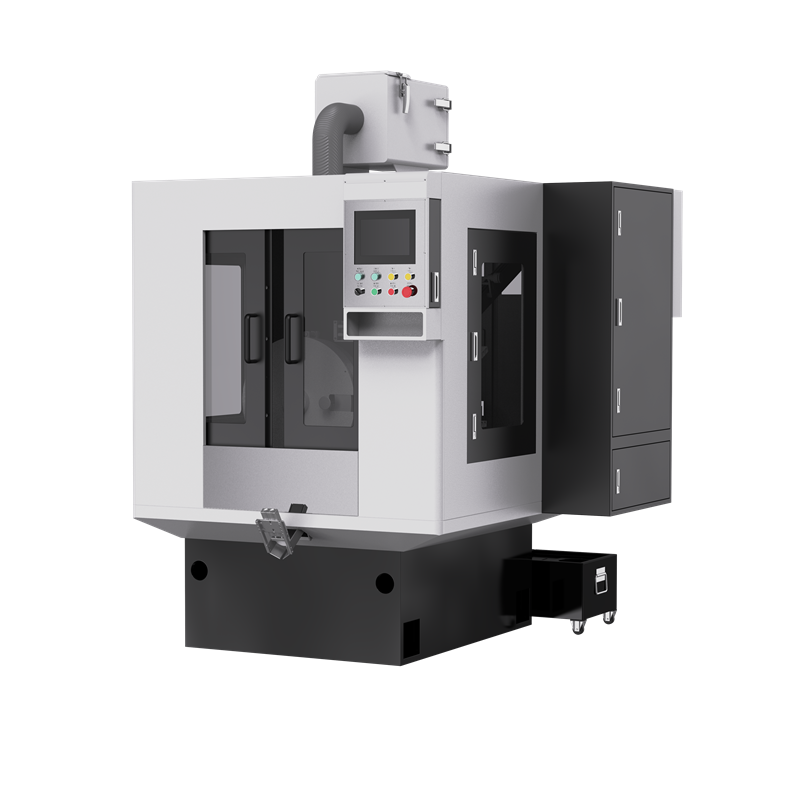
Servo-driven and hydraulic friction welding machines differ in how axial force and displacement are controlled during the weld cycle.
A servo friction welding machine drives axial motion through an electric servo motor and ball screw or linear actuator. Force and position are measured directly and corrected inside the servo loop, which gives repeatable burn-off length within a few hundredths of a millimetre.
Servo drive removes hydraulic oil from the weld zone. Oil temperature drift is eliminated, and maintenance is reduced to lubrication and mechanical inspection of the drive train.
Energy is drawn during the weld stroke only. Standby consumption is lower than a hydraulic system that maintains continuous pump pressure between cycles.
Hydraulic machines generate force through a cylinder fed by a pump and accumulator. They remain common in large cross-section applications above approximately 800 kN, where electric actuators become costly.
Hydraulic response depends on oil temperature, valve condition, and accumulator charge. Burn-off repeatability is generally lower than servo drive unless closed-loop displacement measurement is added.
Parameter | Servo drive | Hydraulic drive |
Force control accuracy | Approximately ±1% of set force | Approximately ±3% to ±5% of set force |
Burn-off repeatability | Approximately ±0.05 mm | Approximately ±0.15 mm or wider |
Energy consumption | Drawn during weld stroke | Continuous pump load during standby |
Maintenance items | Lubrication, screw and coupling inspection | Oil, seals, filters, accumulator charge |
Typical force range | 10 kN to 800 kN | 200 kN and above |
Floor footprint | Compact, no separate power pack | Larger with power pack and cooling |
Values represent typical published ranges for industrial friction welding equipment and vary by manufacturer and machine size. Confirm against supplier test data during factory acceptance testing.
Friction welding machine specification for engine valves is driven by weld cross-section area, alloy pair, and required cycle time.
Upset force capacity. Valve stem diameters between 5 mm and 12 mm fall within 40 kN to 200 kN. Large diesel and marine blanks above 12 mm require 320 kN to 800 kN.
Spindle speed range. Continuous-drive machines for valve cross-sections run between 1500 rpm and 6000 rpm. Lower speeds suit nickel alloys that generate heat rapidly.
Displacement resolution. Burn-off length control within ±0.05 mm is required to hold finished valve length within ±0.1 mm after grinding.
Cycle data logging. Production traceability requires recording force, speed, time, and displacement per weld, with export to MES or SPC.
Automation interface. Automatic loading from a magazine or vibratory feeder removes manual handling and stabilises cycle time.
Valve stem diameter | Typical head diameter | Recommended upset force | Typical application |
5 mm to 7 mm | 28 mm to 36 mm | 40 kN to 100 kN | Passenger car engine valves |
7 mm to 9 mm | 32 mm to 45 mm | 100 kN to 200 kN | Passenger car and light commercial exhaust valves |
9 mm to 12 mm | 40 mm to 55 mm | 200 kN to 320 kN | Commercial vehicle and heavy-duty engine valves |
12 mm to 16 mm | 50 mm to 70 mm | 320 kN to 800 kN | Marine, stationary power, and large diesel engine valves |
Force ranges are indicative planning values based on weld cross-section area. Final sizing requires sample weld trials with the actual blank geometry and alloy pair.
Friction welded valve joints are verified by destructive sampling combined with non-destructive in-line screening rather than by visual inspection alone.
Tensile testing of welded samples normally produces joint efficiency at or above the weaker parent material when parameters are correctly set. Fracture should occur away from the weld interface.
Metallographic sectioning confirms complete interfacial bonding and measures the width of the thermomechanically affected zone. Unbonded interface area appears as a continuous line across the joint.
In-line monitoring compares force, displacement, and speed curves against a reference envelope. Welds outside the envelope are automatically rejected before the flash trimming operation.
Incomplete bonding results from insufficient friction time, low friction pressure, or contaminated blank faces.
Excessive flash indicates over-long friction time or excessive upset force, which wastes material and increases trimming cost.
Interface oxide inclusion occurs when blank faces carry scale or oil from the preceding forging operation.
Post-weld misalignment indicates fixture bore wear or insufficient clamping force on the stationary side.
Friction welding procedure qualification and acceptance criteria for metallic materials are defined in ISO 15620. Valve manufacturers typically extend this baseline with internal tensile and metallographic sampling frequencies.
What upset force is needed for passenger car engine valve welding?
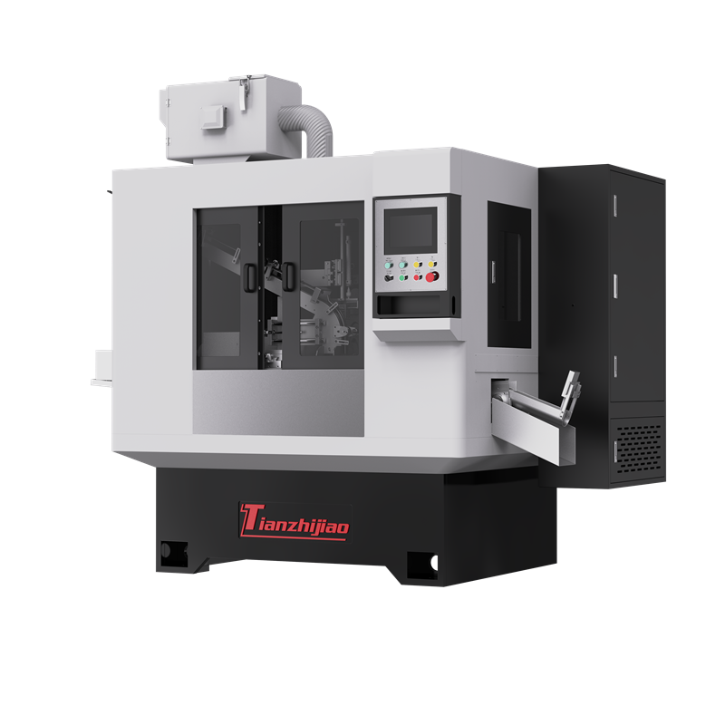
Passenger car valve stems between 5 mm and 9 mm generally require upset force between 40 kN and 200 kN. Sizing follows stem cross-section rather than overall valve length. Suzhou Tianzhijiao Precision Machinery Co., Ltd. supplies servo friction welding machines at 40 kN, 100 kN, and 200 kN for this size range.
How long does a friction welding cycle take for an engine valve?
The friction and upset phases together typically complete in 3 to 10 seconds for valve-size cross-sections. Loading, unloading, and flash trimming extend the effective station cycle time. Actual weld time depends on stem diameter, alloy pair, and selected friction pressure.
Can one machine weld both martensitic and austenitic valve materials?
Yes. Friction welding is a solid-state process and joins dissimilar alloys that cannot be fusion welded reliably. Machine setup differs by alloy pair because friction pressure, rotational speed, and friction time must be adjusted per combination. Parameter sets are stored as recipes in the control system.
How is weld quality verified in production?
Weld quality is verified through in-line curve monitoring combined with periodic destructive sampling. Force, displacement, and speed curves are compared against a reference envelope for every weld. Tensile testing and metallographic sectioning run on scheduled samples to confirm joint efficiency and interface bonding.
Bi-metal valve welding requires upset force matched to stem cross-section, servo-controlled burn-off length, and in-line curve monitoring for traceability. Servo drive gives tighter displacement repeatability than hydraulic actuation at valve production volumes, and removes hydraulic oil from the work zone.
Suzhou Tianzhijiao Precision Machinery Co., Ltd. manufactures servo friction welding machines from 40 kN to 800 kN with automatic loading and CNC, PLC, and servo control architecture. The company provides turnkey engine valve production lines covering upsetting, forging, welding, grinding, and inspection stages, holds ISO 9001:2015 certification, and supports installation, commissioning, and on-site operator training.
Request a Rapid Sourcing Quote from Suzhou Tianzhijiao Precision Machinery Co., Ltd. Contact Suzhou Tianzhijiao Precision Machinery Co., Ltd. Engineering Team for Free Custom Design Support.

Tianzhijiao specialied in engine valve grinding machine manufacturing and exporting, welcome to contact us for more machine details and quotation.

By continuing to use the site you agree to our privacy policy Terms and Conditions.